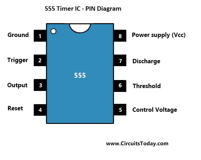
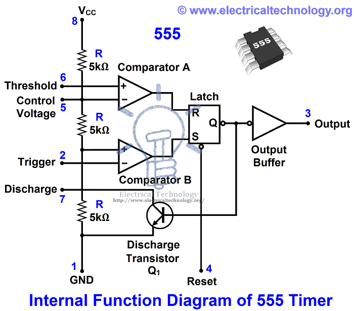
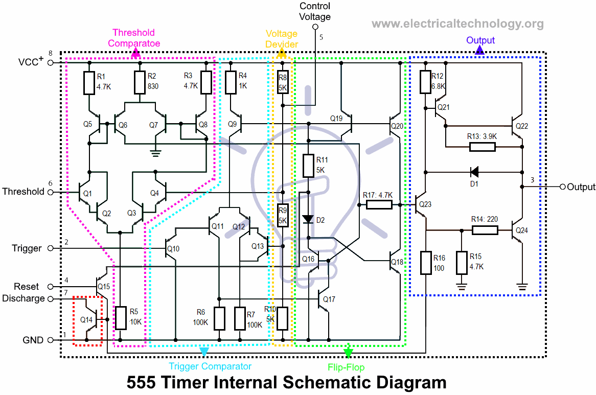
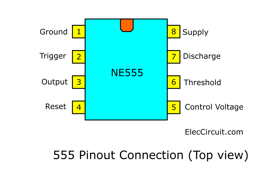
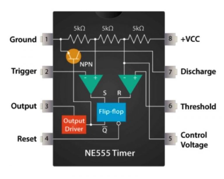
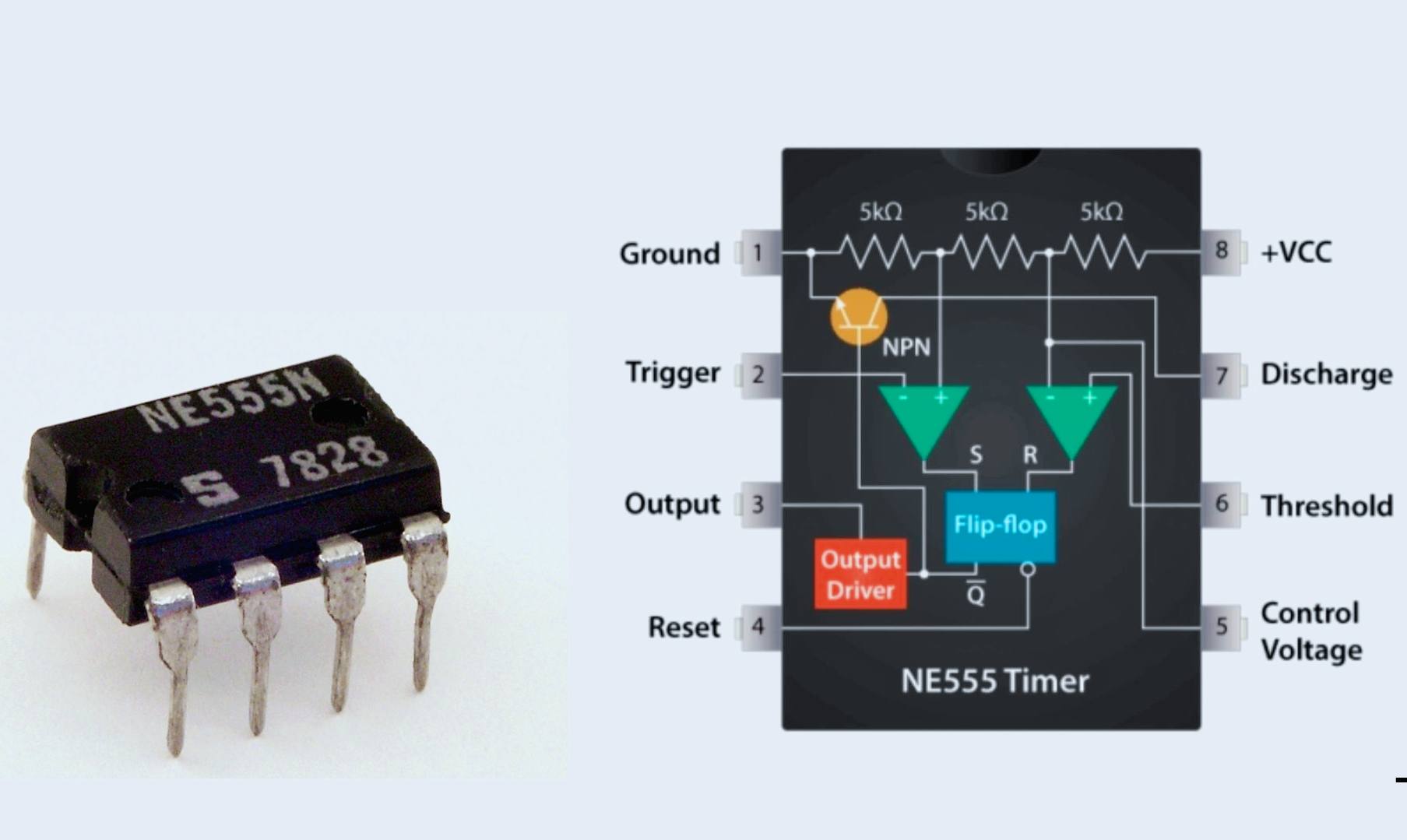
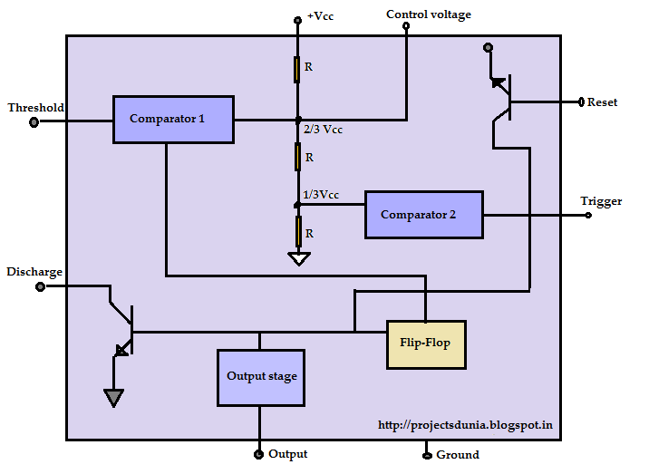
The 555 Timer IC is available as an 8-pin metal can, an 8-pin mini DIP (dual-in-package) or a 14-pin DIP. The pin configuration is shown in the figures. This IC consists of 23 transistors, 2 diodes and 16 resistors. The use of each pin in the IC is explained below.. That’s one IC 555 for every 7 people in the world. The Signetics Company is owned by Philips Semiconductor. If we look at the internal block diagram of IC 555 we find three 5K ohm resistors connected in series for deciding the timing factor, so probably that’s how the device got its name IC 555 timer.

Ic 555 Pin Diagram Explanation
555 Timer IC Electronic Circuits and DiagramsElectronic Projects and Design
555 Timer IC Types, Construction, Working & Applications
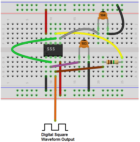
How to Build a Clock Circuit with a 555 Timer
12+ 555 Timer Ic Pin Diagram Robhosking Diagram

555 Timer Pinout
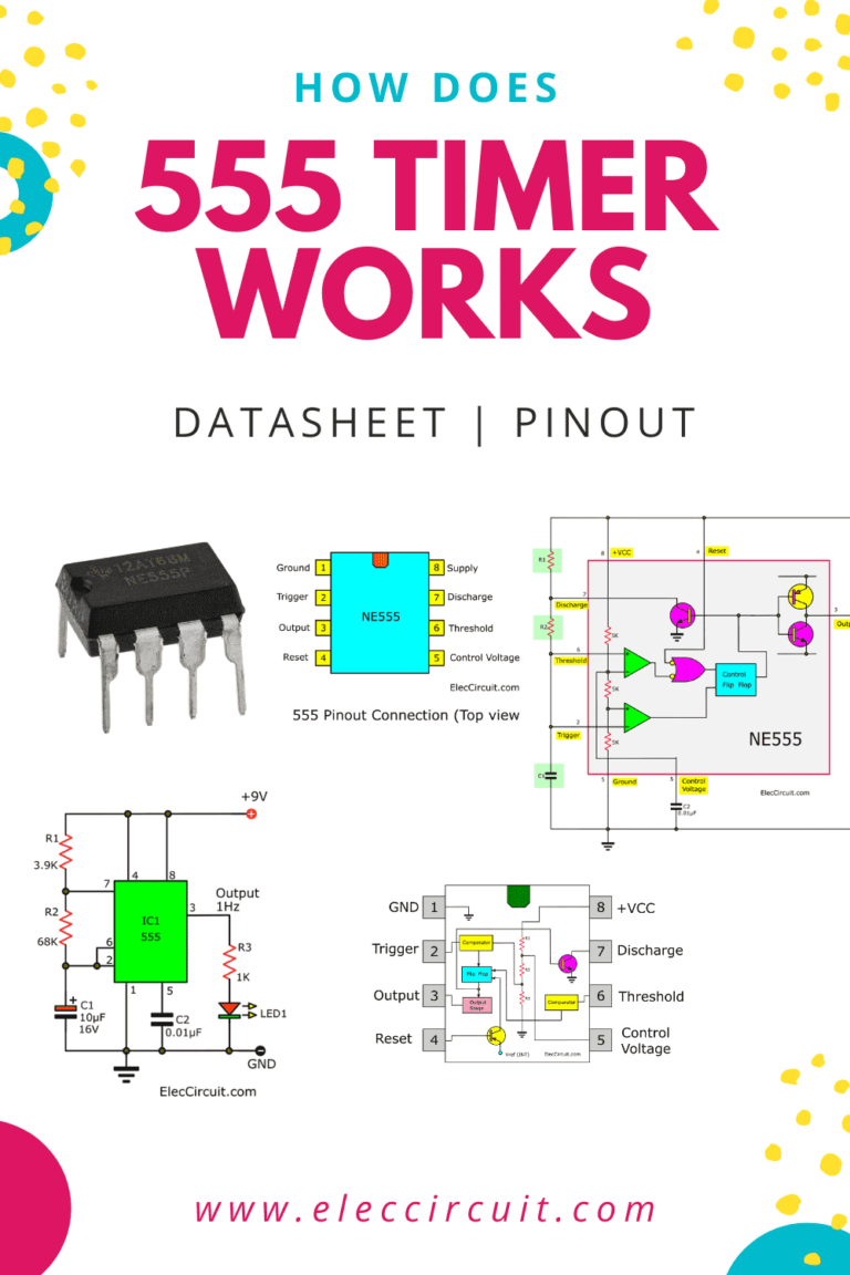
How does NE555 timer circuit work Datasheet Pinout

555 Timer Circuit Diagram Headcontrolsystem
» Working of 555 timer IC explained » 555 timer IC » Hackatronic

How to make Time Delay Circuit Using 555 Timer

555 Timer Ic Working Principle Block Diagram Circuit Schematics Circuit Diagram
» Working of 555 timer IC explained » 555 timer IC » Hackatronic

Schematic 555 Timer Circuit Diagram / LM555 Electronics Schematic Diagram Three Stage Cycling
How does NE555 timer circuit work Datasheet Pinout
555 Timer IC Introduction, Working and Pin configuration PROJECTSDUNIA

Introducing 555 Timer IC Tutorial Random Nerd Tutorials

555 Timer IC Features, Pinout, Working, Circuit, Operating Modes

555 Timer IC Working, Pin Diagram, Examples Astable, Monostable, Bistable YouTube
555 Timer How It Works

555 Timer 2. Monostable Multivibrator Configuration CircuitBread
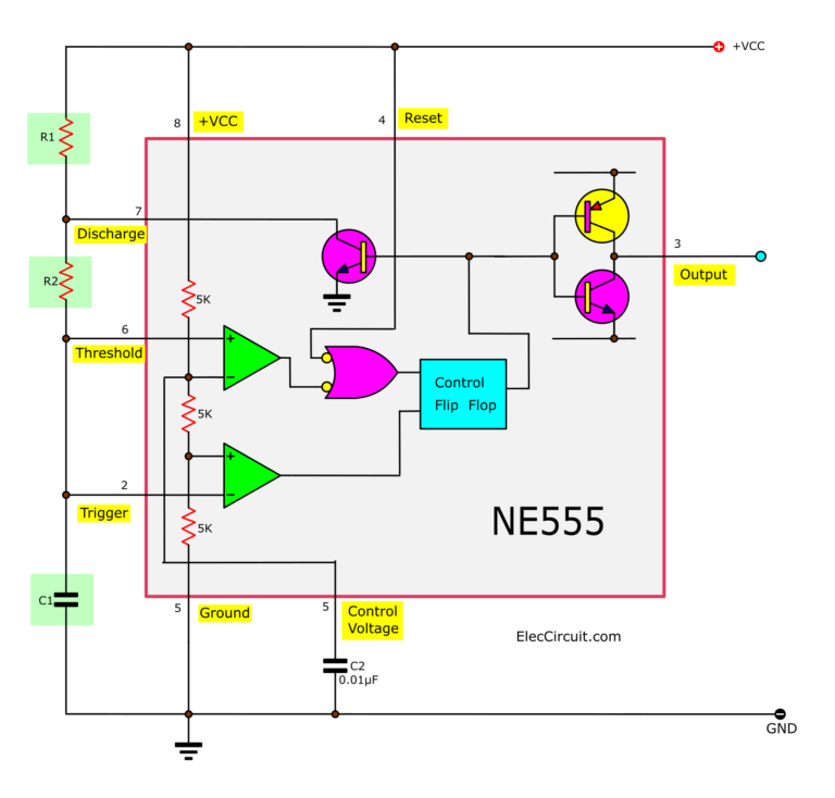
The 555 timer IC is a very cheap, popular and useful precision timing device which can act as either a simple timer to generate single pulses or long time delays, or as a relaxation oscillator producing a string of stabilised waveforms of varying duty cycles from 50 to 100%.. 555 Timer Block Diagram • Pin 1. – Ground, The ground pin.. The 555 timer is an integrated circuit, it is extremely versatile and can be used to build lots of different circuits. The EN555 is usually used to generate continuous series of pulses. These series of pulses allow you to continuously blink an LED, for example. The 555 timer can operate in three different modes:
